J1939 Protocol
The SAE J1939 set of profiles is based on the
Controller Area Network (CAN) data link layer (ISO 11898-1) using the extended frame format (29-bit identifiers).
Several documents have undergone revision after the initial publication in 1998. The specifications have been added to, parts taken
off and clarified. The set of specifications, include:
-
• J1939/11 Physical Layer (250 kbit/s, shielded twisted pair)
-
• J1939/12 Physical Layer (twisted quad of wires and active bus termination)
- • J1939/13 Off-Board Diagnostic Connector
-
• J1939/15 Reduced Physical Layer (250 kbit/s, unshielded twisted pair)
- • J1939/21 Data Link Layer
- • J1939/31 Network Layer
- • J1939/71 Vehicle Application Layer
- • J1939/73 Application Layer Diagnostics
- • J1939/81 Network Management
The naming of the layers is not always compliant to the OSI reference model and to CiA's recommended terminology. The J1939/21 and
J1939/31 define partly an application layer, and the J1939/71 and J1939/73 specify an application profile.
SAE J1939/11
This physical layer specification is based on the ISO 11898-2 standard (high-speed CAN physical layer). It defines a single, linear,
shielded twisted-pair of wires running around the vehicle linking each of its ECUs together. The topology is supposed to be a linear
bus running at 250 kbit/s with termination resistors to reduce reflections.
A J1939 network can be made of multiple bus sections, each one linked with a bridge. The main function of the bridge is to provide
electrical isolation between different segments so that electrical failure of one system will not cause such failure in an adjacent
system. For example, the failure of the CAN/J1939 system on the trailer should not cause the failure of the truck's tractor main
CAN/J1939 control system. The maximum number of ECUs is 30, and the maximum bus length is 40 m.
SAE J1939/21
The SAE J1939/21 is the heart of the J1939 set of specifications. It describes commonly used messages such as Request,
Acknowledgement, and Transport Protocol messages. The Transport Protocol specifies the breaking up of large amounts of data into
multiple CAN-sized frames, along with adequate communication and timing to support effective frame transmission between nodes. Slight
modifications have added flexibility to the Transport Protocol, allowing the sender (server) of data to specify the number of CAN
frames to be sent at any one time. Previously, this number was greatly determined by the receiver's (client's) limitations in the
number of frames it could receive.
SIMMA ENEESDEDEXcRLENCceE
The 29-bit identifier comprises the following sub-fields: priority, reserve, data page, PDU format, PDU specific, and source address.
The source address field ensures unique CAN identifiers, so no two nodes can ever transmit the very same CAN identifier. In the
beginning, J1939 grouped several parameters (signals) together into a Parameter Group (PG). Each PG was then assigned a number: its
PGN (Parameter Group Number). The PGN identifier contained a reserve bit, a data page bit, a PDU format field, and a PDU-specific
field. This structure has since caused some confusion with regard to PDU1-type (destination-specific) messages. Since the
PDU-specific (group extension) field becomes the Destination Address in a PDU1 message, the question arose if the PGN changes, which
it does not. The PGN is a static number referring to the data being transmitted and should be considered independently of the CAN
identifier.
SAE J1939/31
This specification describes bridge functionality, how CAN messages from one network to another are transferred. The message filter
function in the bridge reduces the transmission of CAN messages in the individual network segments.
SAE J1939/71
The so-called application layer (in CiA terms it is an application profile), all parameters as well as assembled messages called
parameter groups are specified. Each CAN message is referenced by a unique number, the PGN (parameter group number). The latest
release of the J1939/71 document incorporates several approved additions, and brings the total number of defined messages up to
almost 150.
New message additions support anti-theft, fuel-specific, turbocharger, ignition, and tire pressure functions, among others. These
additions and enhancements include the addition of the "source address of controlling device" parameter to several engine,
transmission, and brake controller messages. Inclusion of this parameter in a message will allow the receiving device to identify the
original source of the message (e.g., a particular device from a bridged network).
SAE J1939/73
Additions to the diagnostics document (J1939/73) involve memory access, start/stop functions, binary data transfer, security, and
calibration information. Memory access is provided with security levels. The start/stop message is used during diagnostics
performance, to stop other devices from broadcasting (including nodes providing bridges to other networks). Revisions of the J1939/73
document also provide clarification regarding DTC (diagnostic trouble code) encoding in the data field. This encoding, previously
interpreted differently by various manufacturers, was standardized, utilizing the reserved bit as the Conversion Method (CM) bit.
SAE J1939/81
The J1939/81 Draft includes state diagrams for initialization and more clearly defines constraints on the use of addresses. The
J1939/82 Draft specifies the proper procedure for self-compliance and presents a scripting language that tightly defines compliance
processes, and the J1939/83 Tutorial Draft provides an explanation of J1939.
Simma Software, Inc. specializes in real-time embedded software for the automotive industry.
Products and services include protocol stacks, bootloaders, device drivers, training, and consultation on the following
technologies:
J1939, CAN, J1587, J1708, J2497, J1922, ISO 15765, CANopen, UDS, XCP, LIN.
Simma Software, Inc.
5940 South Ernest Drive
Terre Haute, IN 47802
Toll Free: 888-256-3828
Fax: 208-445-2912
What is CAN?
- CAN stands for Controller Area Network
- CAN is a form of serial communications (think sequential, 1 bit after another... )
- Multidrop bus meaning all ECUs are connected to the same set of wires.
-
CAN transmits data with a binary model: 0 is called a dominant bit and a 1 is called a recessive bits.
CAN Frames
- CAN uses four different types of frames for communicating information and the state of the bus.
- Data frame (used by CAN to send data)
- Request frame (used by CAN to request data)
- Error frame (used by CAN to indicate error)
- Overload frame (used by CAN to insert a delay)
CAN Data Frame
- A CAN data frame uses the standard communication architecture of a header followed by data.
- The header is known as the identifier. It is either 29 bits (CAN 2.0B) or 11 bits (CAN 2.0A)
- The data is sent as bytes and is somewhere from 0 to 8 bytes in length.
- Example: "984 1,2,3,4"
CAN 2.0A Format
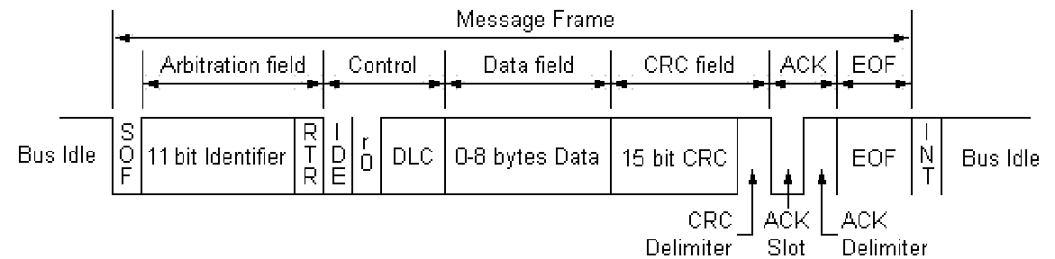
- SOF: Start of frame (start bit)
- ID: Message identifier (indicates msg priority)
- RTR: Remote transmission request
- IDE: Identifier extension bit (2.0A or 2.0B)
- r0: Reserved bit. Sent as dominant.
- DLC: Data length code. Valid range 0 - 8.
- CRC D: CRC delimiter. Marks end of CRC field.
- ACK S: Used for receiver to ACK msg. Sent as recessive.
- ACK D: Marks end of ACK field.
- EOF: End of frame. (stop bit). Sent as 7 recessive bits.
- INT: Intermission. Sent as 3 recessive bits.
CAN 2.0B Format

-
SRR: Substitute request bit. Sent as recessive. This is simply a placeholder bit to ensure compatibility between 2.0A and 2.0B
because 2.0A has RTR.
Bit Stuffing
- 5 consecutive bits, 6th will be opposite.
- Allows for clock synchronization.
- Synchronization happens on recessive to dominant edges.
Questions???
- What are the names for the two types of bits?
- What is the DLC field for?
- What is bit stuffing?
- What questions do you have?
Physical Layer
- Bus is made up of two wires: CAN_H and CAN_L. Terminate with 120 Ohm resistors.
- Bus is differential. Voltage drop from CAN_H to CAN_L determines 0 or 1.
- Dominant bit(0): CAN_H=3.5V, CAN_L=1.5V
- Recessive bit(1): CAN_H=2.5V, CAN_L=2.5V
CAN Bus Example

- J1939 defines physical layer parameters. (e.g. max backbone length)
CAN ID = 0x1dffffff
(1/1101/1111/1...)

Bus Arbitration
- It's what happens when two or more ECUs start to transmit at the same time.
- Every transmitter must make sure what it sends is also what is on the bus.
- If there is a difference, then the CAN controller stops.
- The winner will always be the CAN messages with the lowest identifier.
- Non destructive.
Bus Arbitration Example
| ECU #1 |
0 |
1 |
0 |
0 |
0 |
1 |
| ECU #2 |
0 |
1 |
0 |
0 |
1 |
RX |
| ECU #3 |
0 |
1 |
1 |
RX |
RX |
RX |
| Bus |
0 |
1 |
0 |
0 |
0 |
1 |
Questions
- What is bus arbitration used for?
- Who wins bus arbitration?
- Is CAN point to point or multidrop?
- What are the voltage levels for dominant and recessive bits?
- What questions do you have?
J1939 Overview
- Uses CAN 2.0B
- Replaces J1587 and J1708 (although both co-exist on some vehicles today)
- Used on commercial vehicles (i.e. tractor/trailers, cement mixers, military trucks)
J1939 Message Big Picture
-
Just as CAN is centered around the ID, J1939 is centered around PGN. PGN is defined by the CAN ID.
- PGN: Parameter Group Number
- For example, PGN 65215 is "Wheel Speed Information". Data comes in data field.
- Most PGNs are 8 bytes long. Multibyte variables are sent least significant byte first.
-
Typically 0xFF means "data isn't available", 0xFE means "error". Valid range is 0-250. Check MSB for multibyte variables.
CAN ID Mapping

- P: Message priority. Must come first.
- EDP: Extended data page. J1939 devices must set to 0.
- DP: Data page. Used to create a second page of PGNs.
- PF: PDU format:
- < 240, PS is destination address. (PDU1 format)
- >= 240, PS is group extension. (PDU2 format)
- PS: PDU specific. Either destination address or group extension.
- SA: Source address of controller application (CA).
J1939 PGN Mapping
-
If PF < 240, then PGN = (DP << 9) + (PF << 8), else PGN = (DP << 9) + (PF << 8) + PS
- Max number of PGNs: (240 + (16 x 256)) x 2) = 8,672
Example J1939 PGN
J1939 Wheel Speed Information
- PGN: 65215 (0xFEBF)
- Priority: 6 (default)
- Length: 8
- TX Rate: 100 ms

J1939 Request PGN
- PGN: 59904 (0xEA00)
- Priority: 6 (default)
- Length: 3
- Destination: Global or specific
- Bytes 1-3: PGN which is being requested
J1939 Proprietary A PGN
- PGN: 61184 (0xFEBF)
- Priority: 6 (default)
- Length: 0 to 1785
- Destination: Specific
- Bytes 0 - 1785: Manufacture specific
- Usage should not exceed 2% of network utilization
J1939 Proprietary B PGN
- PGN: 65280 to 65535 (0xFF00 to 0xFFFF)
- Priority: 6 (default)
- Length: 0 to 1785
- Destination: Global
- Bytes 0 - 1785: Manufacture specific
- Usage should not exceed 2% of network utilization
Questions
- Does J1939 use CAN 2.0B or 2.0A?
- CAN is centered around the ID, J1939 is centered around what?
- What does the PF field tell you?
- What questions do you have?
When 8 Bytes Isn't Enough
- J1939 has a feature for PGNs up to 1,785 bytes. It's called the transport protocol. Two ways:
- Send data to global dst (BAM).
- Send data to specific dst (CM).
-
Both ways are similar when it comes to the data transfer part, but differ how they start and how fast data can be sent.
- Only two PGNs are used: Connection Management and Data Transfer
J1939 BAM Big Picture
- First: Transmit a message to the global address that says:
- I'm about to send the following PGN in multiple packets
- I'm sending X amount of data
- I'm sending Y number of packets.
- Second: Send data, wait 50ms, send data, wait 50ms, ect...
BAM Message
Transport Protocol - Connection Management
- PGN: 60416 (0xEC00)
- Priority: 7 (default)
- Length: 8
- Destination: Global
- Byte 1: Fixed at 32
- Bytes 2-3: Message size in bytes
- Byte 4: Number of packets
- Byte 5: Reserved. Filled with 0xFF
- Byte 6-8: PGN
Data Transfer PGN
Transport Protocol - Data Transfer
- PGN: 60160 (0xEB00)
- Priority: 7 (default)
- Length: 8
- Destination: Global
- Byte 1: Sequence number (1 to 255)
- Bytes 2-8: Data. Any unused locations in last packet should be filled with 0xFF
BAM Example
Example transmission of VIN. PGN 65260 (0xFEEC). Assumes VIN is 17 bytes long and is simply 1 through 17. VIN ends with an asterisk
'*'.
| Time (ms) |
PGN |
DST |
0 |
1 |
2 |
3 |
4 |
5 |
6 |
7 |
| 0 |
60416 |
255 |
32 |
18 |
0 |
3 |
255 |
EC |
FE |
0 |
| 50 |
60160 |
255 |
1 |
1 |
2 |
3 |
4 |
5 |
6 |
7 |
| 100 |
60160 |
255 |
2 |
8 |
9 |
10 |
11 |
12 |
13 |
14 |
| 150 |
60160 |
255 |
3 |
15 |
16 |
17 |
'*' |
255 |
255 |
255 |
Destination Specific Big Picture
-
First: Transmit a RTS message to the specific address that says:
- I'm about to send the following PGN in multiple packets.
- I'm sending X amount of data.
- I'm sending Y number of packets.
- I can send Z number of packets at once.
-
Second: Wait for CTS: CTS says:
- I can receive M number of packets at once.
- Start sending with sequence number N.
- Third: Send data. Then repeat steps starting with #2. When all data sent, wait for ACK.
CM Example

RTS Message
Transport Protocol - Connection Management
- PGN: 60416 (0xEC00)
- Priority: 7 (default)
- Length: 8
- Destination: Specific
- Byte 0: Fixed at 16
- Bytes 1-2: Message size in bytes
- Byte 3: Number of packets
- Byte 4: Total number of packet sent in response to CTS.
- Bytes 5-7: PGN
CTS Message
Transport Protocol - Connection Management
- PGN: 60416 (0xEC00)
- Priority: 7 (default)
- Length: 8
- Destination: Specific
- Byte 0: Fixed at 17
- Byte 1: Max number of packets that can be sent at once. (Not larger than byte 5 of RTS)
- Byte 2: Next sequence number to start with
- Bytes 3-4: Reserved. Filled with 0xFF
- Bytes 5-7: PGN
End of Msg ACK Message
Transport Protocol - Connection
- Management
- PGN: 60416 (0xEC00)
- Priority: 7 (default)
- Length: 8
- Destination: Specific
- Byte 0: Fixed at 19
- Bytes 1-2: Total message size in bytes.
- Byte 3: Total number of packets.
- Byte 4: Reserved. Filled with 0xFF
- Bytes 5-7: PGN
Connection Abort Message
Transport Protocol - Connection Management
- PGN: 60416 (0xEC00)
- Priority: 7 (default)
- Length: 8
- Destination: Specific
- Byte 0: Fixed at 255
- Byte 1: Connection abort reason.
- Bytes 2-4: Reserved. Filled with 0xFF.
- Bytes 5-7: PGN
J1939 Address Claim
- All ECUs must claim an address on the network.
-
Claim an address by sending PGN 60928 with the source address set to the address you want to claim.
-
If another ECU claims the same address, the ECU with the lower value NAME field wins. NAME field is 64 bits long and is placed in
the data field of the address claimed message.
- If an ECU loses, it can attempt another source address.
- Two types: "Single Address" and "Arbitrary Address"
J1939 Address Claimed PGN
- PGN: 60928 (0xEE00)
- Priority: 6 (default)
- Length: 8
- Source: SA requested (254 for Cannot Claim)
- Byte 1-8: NAME field
J1939 NAME Field
-
Arbitrary Address Capable: Specifies if the ECU can choose another source address if it loses the address claim procedure.
- Industry Group: Specifies the industry. (e.g. on-highway or Ag)
-
Vehicle System Instance Group: Identifies a particular occurrence of vehicle system. (e.g. trailer #3)
- Vehicle System: Identifies vehicle system (e.g. trailer)
- Function: Identifies the function (e.g. ABS)
- Function Instance: Identifies the function instance (e.g. ABS #1)
-
ECU Instance: Identifies the ECU instance inside of the function field. Used if you have two ECUs making up an ABS controller.
- Manufacturer Code: Assigned by the SAE to identify your company.
-
Identify Number: Set by manufacturer. If all other fields are the same and two ECUs exist on the network, this field must be
unique. (Last line of defense)
J1939/11 Physical Layer
- J1939/11 Physical Layer
- Max bus length: 40 meters
- Max stub length: 1 meters
- Max node count: 30
- Shielded twisted pair. Shield is connected directly to ground at center of backbone.
- Clock tolerance: +/- 0.05%
- Sample point as close to .875 but not past.
J1939/15 Physical Layer
- Max bus length: 40 meters
- Max stub length: 3 meters
- Max node count: 10
- Unshielded twisted pair.
- Clock tolerance: +/- 0.05%
- Sample point as close to .875 but not past.
- 200-500ns rise and fall time for CAN signal
Document Summary
- J1939: Parent. Includes things not listed elsewhere.
- J1939/11: Physical layer
- J1939/13: Off-board diagnostics connector
- J1939/15: Physical layer
- J1939/21: Data link layer
- J1939/31: Network layer
- J1939/71: Vehicle application layer
- J1939/73: Diagnostics
- J1939/81: Network management
References
- BOSCH CAN Specification
- SAE J1939/11 Physical Layer
- SAE J1939/15 Physical Layer
- SAE J1939/21 Data Link Layer
- SAE J1939/71 Application Layer
- SAE J1939/81 Network Management
Post Class Questions
- E-mail: jrsimma "at" simmasoftware "dot" com
- Phone: 888-256-3828
